Exterior rendering
External Wall Insulation in West Bridgford | Design Details
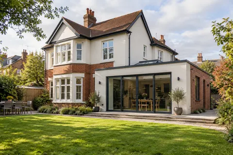
Insulation outside the wall changes its thickness and the way openings and projections sit within it. A bay, shallow sill or retained porch roof can make those changes particularly visible. The project needs a suitable whole-system assessment and design, with the final appearance considered alongside the thermal and moisture requirements.

On this page
Assess the existing wall before drawing the new one
Establish the construction, condition and relevant alterations. Identify existing coverings and any uncertainty about concealed areas. Moisture concerns, damaged render and defective rainwater details need investigation before they are covered. The proposed insulation should not be used to hide an unresolved problem simply because its final surface will look new.
The thermal design and applicable requirements need competent consideration for the actual building. No standard thickness or predicted saving is supplied here because those depend on information that has not been established for an individual property. A town-wide housing profile cannot substitute for that assessment.
Where traditional fabric is present, material and moisture compatibility require particular care. Later additions may have different construction and need separate treatment. The design should explain these distinctions and any transitions rather than assume that one visible colour means an identical wall build-up across the property.
Include the limits of any survey in the design brief so concealed construction is not treated as confirmed information.
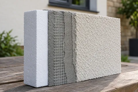
- Existing wall Prepared; fittings removed and the base track fixed above ground level.
- Insulation boards Bonded with adhesive and, in most systems, mechanically fixed to the wall.
- Basecoat with mesh Reinforcement mesh embedded across the board joints and around openings.
- Primer Where the system requires it.
- Finish render A thin-coat finish that weatherproofs the insulation.
Wall on the left, finish on the right. Not to scale: coats, thicknesses and primers follow the chosen manufacturer’s system and the condition of the wall.
Test the proportions at windows and bays
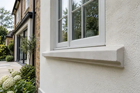
Draw the finished external line at openings, including reveals and sills. The added build-up changes their apparent depth and the relationship with frames. A bay has several faces and corners, so small changes can affect its overall shape. The design should resolve these connections rather than leave the installer to decide how much space remains around each opening.
Sill projections and water-shedding details must work with the completed wall. A decorative brick band or stone feature may need a specific decision about retention and the adjoining insulation. Do not assume that leaving a feature uncovered is technically equivalent to a simple colour change. The thermal and physical transition needs consideration.
If window replacement is planned, coordinate it before the insulation details are final. Frame positions and dimensions can alter the proposal. Keep the window and wall information together so the two packages do not develop independently and meet awkwardly on site. A sample of the final render cannot resolve a dimensional conflict.
For an opening window within the bay, check the proposed detail against its full movement rather than a drawing of the closed frame alone. Handles, hinges and cleaning access may need consideration at tight returns. Confirm any adjustment with the window and insulation designers before the finished dimensions are accepted.
Resolve roofs, bases and attachments as part of the system
Eaves, verges, porch roofs and copings relate to the original wall line. The thicker build-up may require changes or specific connections. Ask for the relevant details and identify which trade carries them out. The insulation contractor should not be left to improvise around an unchanged roof edge whose suitability has never been assessed.
Pipes, cables, lights, vents and other attachments need supported fixing and penetration arrangements. Record their final positions, temporary removal and reinstatement responsibilities. A longer generic fixing is not a complete design through an insulated system. Maintenance access to these fittings should remain practical after the work.
At the base and at uninsulated returns, use the specified termination details appropriate to the building. Adjacent paving, soil and boundaries can affect the arrangement. The visible line should follow a suitable design rather than be extended or shortened solely to satisfy a colour preference.
| Location | Design information |
|---|---|
| Bay and windows | Finished dimensions, reveals and sills |
| Roof edge | Connection to the added build-up |
| Retained feature | Thermal and material transition |
| Attachment | Supported fixing and weathering detail |
| Base and return | Specified termination for actual conditions |
Select the exterior finish within the complete specification
A silicone decorative finish may form part of the system, but it does not define the insulation, fixings or base layers. Ask for the named complete system and the relevant design information. Components should follow a supported specification rather than be chosen independently because their colours or availability happen to suit the programme.
Use representative samples to assess grain and colour beside retained materials. The whole-house appearance matters, particularly where some elevations remain uninsulated or receive different work. The house rendering guide helps frame those visual decisions, while silicone rendering explains the decorative surface without replacing the insulation design.
Check the relevant planning and building requirements, including designation records where applicable. Edwalton’s conservation boundary is specific and should not be confused with all West Bridgford. Keep any necessary advice or decisions with the project information so the installed scheme reflects the actual requirements.
Plan inspection and future alterations
Some details become concealed as the system is installed. The project should identify appropriate inspection stages and useful records before that happens. A photograph of the completed colour cannot demonstrate every underlying fixing or interface. Keep the accepted drawings and approved changes with the installation information.
At handover, provide the owner with the relevant system and care details. Future drilling, attachments or repairs need to recognise the insulation behind the finish. A later contractor should not discover it only after opening a hole. A concise summary of the installed build-up can make the more detailed information easier to use.
If damage develops, assess the complete affected system rather than applying a superficial patch automatically. The render repair guide provides starting questions, but the specific installation remains the technical reference. Similarly, any later colour treatment should be checked for compatibility before a new coating is applied.
Common questions
Can insulation alter the look of a bay?
Yes. Added thickness affects reveals, corners and projections. The design should show those changes before work is agreed.
Can decorative brick bands remain visible?
That requires a specific design for the retained feature and surrounding system. It should not be treated as an ordinary paint boundary.
What should an energy-saving estimate explain?
It should identify the assessed building, proposed work and assumptions about its use. A figure for a different property cannot establish the likely result for your house, even where the finished walls look similar.
Why keep hidden-detail photographs?
They can help document agreed inspection stages and assist later work, although photographs alone do not replace the necessary competent checks.
See housing and planning information for West Bridgford and nearby places, including the source and geography behind each figure.